
Flow Simulation using the Compuplast CAE Virtual Extrusion Laboratory
Why Flow Simulation?
The simulation of polymer flow processes is extremely important because it allows us the opportunity to eliminate the need for costly trials using real materials and real people on real plant.
A range of process scenarios can be created in a virtual environment and conclusions drawn as to their suitability in minutes rather than days or weeks.
Compuplast provide software for almost every extrusion process (figure 1).
What Processes can we simulate?
- Pipe extrusion-mono & co-extruded
- Film-mono & multi layer
- Profile extrusion-mono & multi layer
- Flat die (coathanger dies)
- Side fed dies
- 2D and 3D simulations
- Single screw extrusion
Removing the black art?
Much die design has historically involved a significant degree of black art, Compuplast firmly believe this can be removed via the use of their software which melds vast industrial experience with academic rigour.
Considerable mathematics is involved in a subject as complex as flow simulation, however, Compuplast have enabled toolmakers and managing directors alike to solve process problems at the touch of a button with only a modicum of training.
This has been made possible by a program front end which effectively links recognisable process features with the complex procedures necessary to solve what are non-trivial problems.
All of the Compuplast programs share a common materials database from which, either library or user measured data, can be drawn. The ability to enter user measured data is enhanced by providing a range of fitting techniques for the modelling of such data.
If the user has access to rheometry, more in-depth insight can be gained by supplementing shear data with elongational information.
Figure 2 shows the 2DFEM solved solution for polymer flowing from a typical rheometer bore into a 1mm diameter die.
Figure 3 uses the zoom function to highlight the important die entry region where extension rates and temperature are interrogated along a selected streamline.
The 2DFEM program also enables co-extruded pipes to be modelled, and figure 4 shows the resulting solution.
Flow behaviour is very important at the interface since any instabilities developed here can go on to cause very real problems.
Compuplast have incorporated the Leonov viscoelastic model to their latest release, and this has enabled elastic behaviour at the interface to be predicted.
Research has shown that an oscillation of extension rate and first normal stress difference can indicate the onset of instabilities (figure 5).
The instabilities have been shown to exist in different forms, ranging from high frequency zig zag instabilities to low frequency wave types (figure 6).
Figure 7 shows the flow distribution in a complex profile during a die balancing procedure using the Compuplast Profile Die module. This and many more solutions are possible using the Compuplast suite of programs.
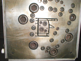
A complex PVC window profile die
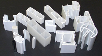
Typical window frame profiles
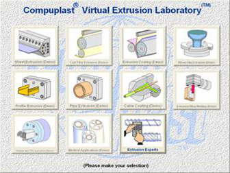
Figure 1 - The Compuplast Virtual Extrusion Laboratory enables almost all extrusion processes to be simulated
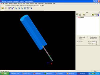
Figure 2 - Simulated flow inside the die of a capillary rheometer using the 2DFEM module
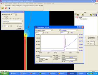
Figure 3 - Interrogating extension rates at the die inlet-note the sharp rise on entering the die.
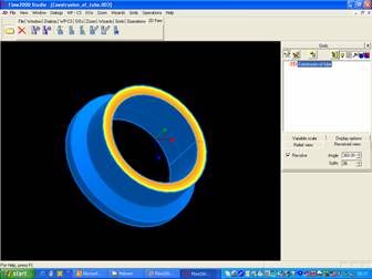
Figure 4 - A coextruded pipe
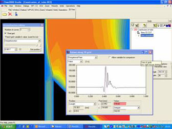
Figure 5 - Oscillation of the extension rate at the interface
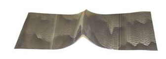
Figure 6 - Multi-frequency instabilities in a film extrusion
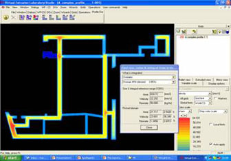
Figure 7 - Flow in a complex profile extrusion during a balancing procedure
Telephone:
01299 251 914
Our postal address:
Fleming
Polymer Testing Ltd,
Holly House
Hartlebury
Kidderminster
DY11 7TE UK